Tag: VMC

  • Deploy, Run, and Manage Any Application with VMware Cloud Director Content Hub

    Deploy, Run, and Manage Any Application with VMware Cloud Director Content Hub

    In today’s fast-paced digital landscape, businesses require agile and scalable solutions to deploy and manage their applications efficiently. VMware Cloud Director Content Hub (VDCH) introduced in VMware Cloud Director 10.5, offers a robust platform for a simplified and automated way to deploy, run, and manage a wide range of applications. In this blog, we’ll explore the key features and benefits of VMware Cloud Director Content Hub and how it streamlines the application deployment process.

    What is Content Hub ?

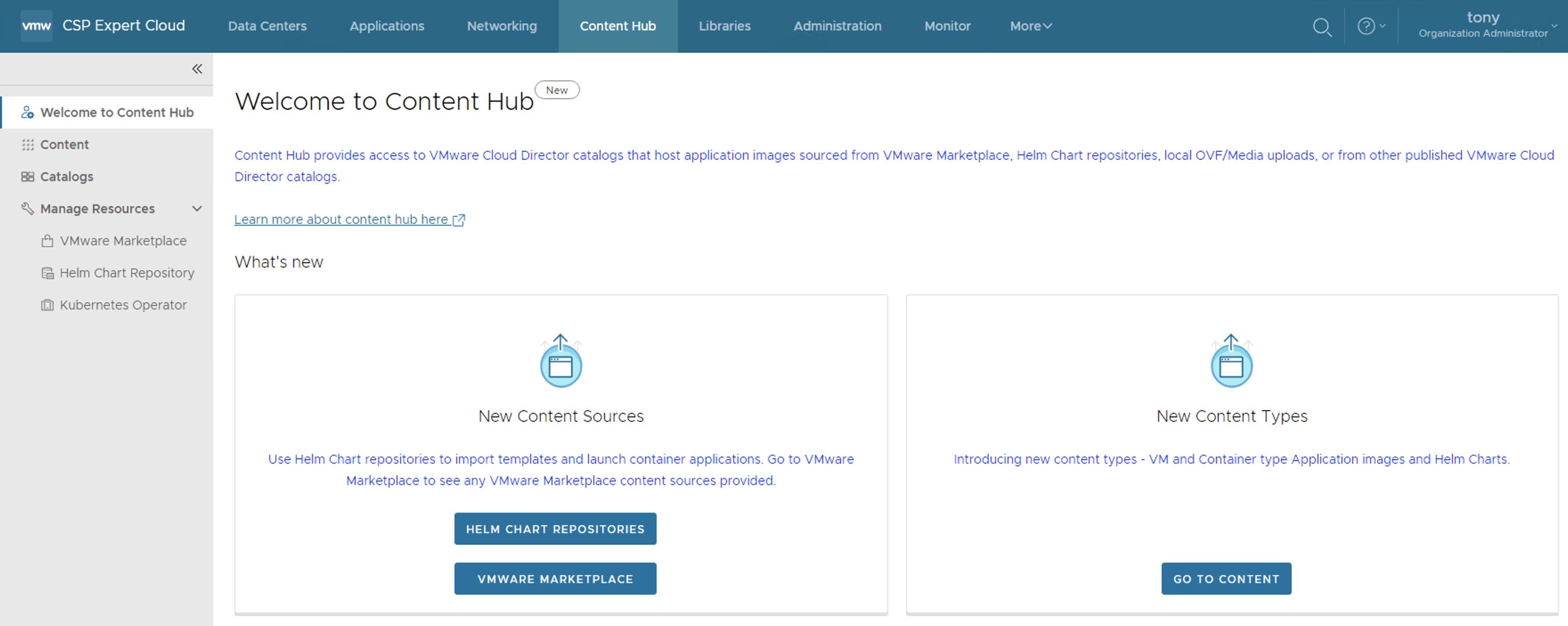
    Content Hub, introduced in VMware Cloud Director 10.5, serves as a convenient tool that unifies the interface for accessing both VM and container-based content. This feature seamlessly integrates external content sources, such as VMware Marketplace and Helmchart Repositories, into the VMware Cloud Director environment.

    By incorporating external sources, content can be seamlessly brought into the catalogs of VMware Cloud Director, ensuring its immediate availability for users. With the integration of Content Hub, VMware Cloud Director introduces an interface oriented towards applications, enabling users to effortlessly visualize and retrieve catalog content, thus elevating the overall content management experience.

    As a result of these enhancements, catalog items are presented as “Application Images,” highlighting crucial application information like the application’s name, version, logo, screenshots, and other pertinent details necessary for the consumption of the application

    Integration with VMware Marketplace

    To integrate Marketplace with VMware Cloud Director, a Cloud Provider needs to create a Marketplace Connection and then share it with one or more tenant organisations. Here is the procedure:

    • Cloud Provider must be logged in as a system administrator.
    • Cloud Provider must have access to VMware Marketplace and there generated an API token. (see Generate API Tokens in the VMware Cloud Services Product Documentation)
    • From the left panel, select VMware Marketplace & Click New.
    • The New VMware Marketplace dialog opens, and there enter the following values:

    Integration with Helm Chart Repository

    A Helm chart repository is a named resource that stores all the information required to establish a connection with a Helm chart repository, allows users to browse contents from a remote repository, and imports applications from the repository.

    Cloud Providers and tenants both can create Helm chart repository content connections. Tenants need special RIGHTs that providers can assign to specific tenants based on requirements.

    • From the left panel, select Helm Chart Repository & Click New.
    • The New Helm Chart Repository dialog opens, and there enter the following values:

    • Password-protected Helm chart repositories are also supported. 
    • You can create multiple Helm chart repository resources in VMware Cloud Director.

    Share a VMware Marketplace/Helm Chart Repository Resource with tenants

    As a service provider administrator, you can share the configured VMware Marketplace resources with other tenant organizations.

    • Inside VMware Marketplace/Helm Chat Repository, on the left of the name of the connection that you want to share, click the vertical ellipsis and select Share.
    • Share the resource.
    • Select the tenant organizations you want to share the resource with.
    • You can set the individual access level for the respective tenant organization only as Read Only.
    • Click Save.

    NOTE: Since vCD does a DB caching of the helm chart repository items in vCD DB, you can click on Sync which will ensure the latest from the remote repository is cached in vCD DB.

    Roles Required

    A new set of User Roles has been introduced to facilitate users in accessing and managing the Content Hub. Assigning the appropriate user roles to individuals within the organization to grant them access and utilize the Content Hub feature effectively is crucial.

    Right Bundles: A Rights Bundle is a collection of rights for the tenant organization and A Rights Bundle defines what a tenant organization has access to. Rights Bundles are always defined globally, and they can be applied to zero or more tenants.

    Roles: A Role is a collection of rights for a user. A Role defines what an individual user has access to. Roles can either be tenant-specific–defined within a single organization and only visible to that organization, or global–defined globally and applied to zero or more tenants. 

    Putting all the pieces together looks something like this:

    Following are the new RIGHTs introduced to manage CatalogContentSource entities:

    Apply the Above Rights for organizations as well as the user, so that they have enough rights to add and deploy applications.

    Content Hub Operator for Kubernetes Container Service Extention

    To perform this operation, First, you need full control of the Kubernetes cluster, where you are deploying the container applications, and additionally the following VMware Cloud Director rights:

    You must install a Kubernetes operator to allow tenant users to deploy container applications from external content sources. From the top navigation bar, select Content Hub, from the left panel, select Kubernetes Operator, and on the Kubernetes Operator page, select the Kubernetes cluster on which you want to install the Kubernetes operator, and click Install Operator.

    The Install operator on cluster-name dialog opens, on this page Configure the source location of the Kubernetes operator package.

    Select the type of source location for the Kubernetes operator package. VMware Registry location with anonymous access is selected by default.

    (Optional) To configure a custom registry, first, you must clone the Content Hub Kubernetes operator package from the VMware container registry to your custom registry. The Content Hub Kubernetes operator package is in Carvel format and you must use the Carvel imgpkg tool for cloning the package.

    Click Install Operator.

    After a Few minutes it shows “Not Reachable”

    And then finally it turns to “ready”, basically After the installation of the operator completes successfully, the system creates two namespaces under the Kubernetes cluster. In the first namespace, “vcd-contenthub-system”, the Content Hub Operator manager is installed. The second namespace, “vcd-contenthub-workloads”, is empty. This namespace is used to deploy container applications at a later stage.

    Catalog Versioning

    In the previous version of VMware Cloud Director, there was no concept of versioning in catalogs. For instance, when a user imports multiple versions of the same application from external sources into the catalog, each version of the VM or container will be stored and represented (listed) as an individual resource, but from VMware Cloud Director 10.5 onwards, a Virtual Machine application or Container application that was imported with multiple versions either at the same time or at different intervals, Content Hub is capable of managing and structure the versioning of that resource.

    Let’s Deploy a Container Application

    Upon launching an application image that has multiple versions, you will be prompted to choose the specific version of the image you wish to deploy.

    If the Container application is launched, then the Container Application launcher window will open and then you need to provide the application Name, select the version to deploy and select the TKG Cluster.

    (Optional) To customize the application parameters, click Show Advanced Settings.

    Click Launch Application.

    The system deploys the container application. After the deploy operation completes, on the card for the application, the status appears as Deployed. VMware Cloud Director deploys the container application as a Helm release under the vcd-contenthub-workloads namespace to the Kubernetes cluster.

    Either clicking on Application Name or DETAILS, it takes user to details of the application, like Status, Pods Status, Access URLs etc..

    User can use the access URL details to access the application easily

    Deploy an Stateful Container Application

    In this section we will deploy Casandra database using Cloud Director Content Hub, process is simple as we followed in above section, once deployed the application, check the details, here details are different like no access URL, it also created required Persistent Volumes automatically

    it also give visibility to Stateful Set and its status, secrets if any, services and its type as well as other resources. this allow end user to not to check in K8s clusters vs this info is available in vCD GUI.

    Deploy an Virtual Machine Application

    A vApp consists of one or more virtual machines that communicate over a network and use resources and services in a deployed environment. A vApp can contain multiple virtual machines.If you have access to a catalog, you can use the vApp templates in the catalog to create vApps.

    A vApp template can be based on an OVF file with properties for customizing the virtual machines of the vApp. The vApp inherits these properties. If any of those properties are user-configurable, you can specify their values.

    Enter a name and, optionally, a description for the vApp.

    Enter a runtime lease and a storage lease for the vApp, and click Next.

    From the Storage Policy drop-down menu, select a storage policy for each of the virtual machines in the vApp, and click Next.

    If the placement policies and the sizing policies for the virtual machines in the vApp are configurable, select a policy for each virtual machine from the drop-down menu.

    If the hardware properties of the virtual machines in the vApp are configurable, customize the size of the virtual machine hard disks and click Next.

    If the networking properties of the virtual machines in the vApp are configurable, customize them and click Next.

    On the Configure Networking page, select the networks to which you want each virtual machine to connect.

    (Optional) Select the check box to switch to the advanced networking workflow and configure additional network settings for the virtual machines in the vApp.

    Review the vApp settings and click Finish.

    You can see under Applications -> Virtual Applications, VM is getting deployed.

    With Content Hub feature provide can offers centralized content management for application images, vApp and VM templates, and media. VMware Cloud Director now has full control over the deployed and listed images, storing all pertinent information in its database. Unlike the application images imported from App Launchpad, where VMware Cloud Director only listed the imported images and App Launchpad stored all the details and information in its own database as well as It offers ease of use since you won’t have to set up and configure App Launchpad, which would otherwise be an additional task.

  • Infrastructure as Code with VMware Cloud Director

    Infrastructure as Code with VMware Cloud Director

    In today’s fast-paced digital landscape, organizations are constantly seeking ways to optimize their IT operations and streamline infrastructure management. One approach that has gained significant traction is Infrastructure as Code (IaC). By treating infrastructure provisioning and management as code, IaC enables organizations to automate and standardize their processes, resulting in increased efficiency, scalability, and consistency.

    In this blog article, we will explore the concept of Infrastructure as Code and its practical implementation using VMware Cloud Director. We will delve into the benefits and challenges of adopting IaC, highlight the features of VMware Cloud Director, and showcase how the integration of Terraform with VMware Cloud Director can revolutionize IT operations for Cloud Providers as well as customers.

    What is Infrastructure as Code?

    Infrastructure as Code (IaC) is a methodology that involves defining and managing infrastructure resources programmatically using code. It allows organizations to provision, configure, and manage their infrastructure resources, such as compute, network, and storage, through automated processes. By treating infrastructure as code, organizations can leverage the same software development practices, such as version control and continuous integration, to manage their infrastructure.

    Benefits of Infrastructure as Code

    The adoption of Infrastructure as Code brings numerous benefits to cloud providers as well as customers:

    Consistency and repeatability: With IaC, infrastructure deployments become consistent and repeatable, ensuring that the same configuration is applied across different environments. This eliminates configuration drift and minimizes the risk of errors caused by manual configurations.

    Efficiency and scalability: IaC enables organizations to automate their infrastructure provisioning and management processes, reducing the time and effort required for manual tasks. This allows IT teams to focus on more strategic initiatives and scale their infrastructure easily as the business demands.

    Version control and collaboration: By using code repositories and version control systems, organizations can track changes made to their infrastructure configurations, roll back to previous versions if needed, and collaborate effectively across teams.

    Documentation and auditability: IaC provides a clear and documented view of the infrastructure configuration, making it easier to understand the current state and history of the infrastructure. This improves auditability and compliance with regulatory requirements.

    Flexibility and portability: With IaC, organizations can define their infrastructure configurations in a platform-agnostic manner, making it easier to switch between different cloud providers or on-premises environments. This provides flexibility and avoids vendor lock-in.

    Challenges of Infrastructure as Code

    While Infrastructure as Code offers numerous advantages, it also presents some challenges that organizations should be aware of:

    Learning curve: Adopting IaC requires IT teams to acquire new skills and learn programming languages or specific tools. This initial learning curve may slow down the adoption process and require investment in training and upskilling.

    Code complexity: Infrastructure code can become complex, especially for large-scale deployments. Managing and troubleshooting complex codebases can be challenging and may require additional expertise or code review processes.

    Continuous maintenance: Infrastructure code needs to be continuously maintained and updated to keep up with evolving business requirements, security patches, and technology advancements. This requires ongoing investment in code management and testing processes.

    Infrastructure as Code Tools

    There are various tools available in the market to implement Infrastructure as Code. Some of the popular ones include:

    Terraform: Terraform is an open-source tool that allows you to define and provision infrastructure resources using declarative configuration files. It supports a wide range of cloud providers, including VMware Cloud Director, and provides a consistent workflow for infrastructure management.

    Chef: Chef is a powerful automation platform that enables you to define and manage infrastructure as code. It focuses on configuration management and provides a scalable solution for infrastructure provisioning and application deployment.

    Puppet: Puppet is a configuration management tool that helps you define and automate infrastructure configurations. It provides a declarative language to describe the desired state of your infrastructure and ensures that the actual state matches the desired state.

    Ansible: Ansible is an open-source automation tool that allows you to define and orchestrate infrastructure configurations using simple, human-readable YAML files. It emphasizes simplicity and ease of use, making it a popular choice for infrastructure automation.

    VMware Cloud Service Provider Program

    The VMware Cloud Service Provider Program (CSP) allows service providers to build and operate their own cloud environments using VMware’s virtualization and cloud infrastructure technologies like VMware Cloud Director, Cloud Director availability etc… This program enables service providers to offer a wide range of cloud services, including infrastructure-as-a-service (IaaS), disaster recovery, Application as a Service, Kubernetes as a Service, DBaaS and many other managed services.

    Integrating Terraform with VMware Cloud Director

    To leverage the power of Infrastructure as Code in VMware Cloud Director, you can integrate it with Terraform. Terraform provides a declarative language for defining infrastructure configurations and a consistent workflow for provisioning and managing resources across different cloud providers, including VMware Cloud Director. By combining Terraform with VMware Cloud Director, Cloud Providers/Customers can:

    Automate infrastructure provisioning: With Terraform, Cloud providers can define Tenant virtual data center, virtual machines, networks, and other resources as code. This allows for automated and consistent provisioning of infrastructure resources, eliminating manual configuration. I wrote a blog article on how to start with Cloud Director & Terraform which can be found here:

    Ensure consistency and repeatability: Infrastructure configurations defined in Terraform files can be version controlled, allowing for easy tracking of changes and ensuring consistency across different environments.

    Collaborate effectively: Terraform code can be shared and collaboratively developed within teams, enabling better collaboration and knowledge sharing among IT professionals.

    Enable infrastructure as self-service: By integrating Terraform with VMware Cloud Director, organizations can provide a self-service portal for users to provision and manage their own infrastructure resources, reducing dependency on IT support.

    Implementing Infrastructure as Code with VMware Cloud Director and Terraform

    To begin with the Terraform configuration, create a main.tf file and specify the version of the VMware Cloud Director Terraform provider

    terraform {
      required_providers {
        vcd = {
          source  = "vmware/vcd"
          version = "3.9.0"
        }
      }
    }
    
    provider "vcd" {
      url                  = "https://vcd-01a.corp.local/"
      user                 = "admin"
      password             = "******"
      org                  = "tfcloud"
      vdc                  = "tfcloud"
    }

    In the above configuration, replace the url, user, password, org, and vdc values with your own VMware Cloud Director details.Now, let’s define the infrastructure resources using Terraform code. Here’s an example of creating a organization in VMware Cloud Director:

    #Create a new org name "tfcloud"
    resource "vcd_org" "tfcloud" {
      name              = "terraform_cloud"
      full_name         = "Org created by Terraform"
      is_enabled        = "true"
      stored_vm_quota   = 50
      deployed_vm_quota = 50
      delete_force      = "true"
      delete_recursive  = "true"
      vapp_lease {
        maximum_runtime_lease_in_sec          = 0
        power_off_on_runtime_lease_expiration = false
        maximum_storage_lease_in_sec          = 0
        delete_on_storage_lease_expiration    = false
      }
      vapp_template_lease {
        maximum_storage_lease_in_sec       = 0
        delete_on_storage_lease_expiration = false
      }
    }

    Creating Organisation Administrator

    #Create a new Organization Admin
    resource "vcd_org_user" "tfcloud-admin" {
      org               = vcd_org.tfcloud.name
      name              = "tfcloud-admin"
      password          = "*********"
      role              = "Organization Administrator"
      enabled           = true
      take_ownership    = true
      provider_type     = "INTEGRATED" #INTEGRATED, SAML, OAUTH stored_vm_quota = 50 deployed_vm_quota = 50 }

    Creating Org VDC

    # Create Org VDC for above org
    resource "vcd_org_vdc" "vdc-tfcloud" {
      name = "vdc-tfcloud"
      org  = vcd_org.tfcloud.name
      allocation_model  = "AllocationVApp"
      provider_vdc_name = "vCD-A-pVDC-01"
      network_pool_name = "vCD-VXLAN-Network-Pool"
      network_quota     = 50
      compute_capacity {
        cpu {
          limit = 0
        }
        memory {
          limit = 0
        }
      }
      storage_profile {
        name    = "*"
        enabled = true
        limit   = 0
        default = true
      }
      enabled                  = true
      enable_thin_provisioning = true
      enable_fast_provisioning = true
      delete_force             = true
      delete_recursive         = true
    }

    Creating Edge Gateway (NAT Gateway)

    # Create Org VDC Edge for above org VDC
    resource "vcd_edgegateway" "gw-tfcloud" {
      org                     = vcd_org.tfcloud.name
      vdc                     = vcd_org_vdc.vdc-tfcloud.name
      name                    = "gw-tfcloud"
      description             = "tfcloud edge gateway"
      configuration           = "compact"
      advanced                = true
      external_network {
         name = vcd_external_network.extnet-tfcloud.name
         subnet {
            ip_address            = "10.120.30.11"
            gateway               = "10.120.30.1"
            netmask               = "255.255.255.0"
            use_for_default_route = true
        }
      }
    }

    Here is the blog post which covers Tenant OnBoarding on Cloud Director using Terraform:

    Best Practices for Infrastructure as Code with VMware Cloud Director

    Implementing Infrastructure as Code with VMware Cloud Director and Terraform requires adherence to best practices to ensure efficient and reliable deployments. Here are some key best practices to consider:

    Use version control: Store your Terraform code in a version control system such as Git to track changes, collaborate with teammates, and easily roll back to previous configurations if needed.

    Leverage modules: Use Terraform modules to modularize your infrastructure code and promote reusability. Modules allow you to encapsulate and share common configurations, making it easier to manage and scale your infrastructure.

    Implement testing and validation: Create automated tests and validations for your infrastructure code to catch any potential errors or misconfigurations before deployment. This helps ensure the reliability and stability of your infrastructure.

    Implement a CI/CD pipeline: Integrate your Terraform code with a continuous integration and continuous deployment (CI/CD) pipeline to automate the testing, deployment, and management of your infrastructure. This helps in maintaining consistency and enables faster and more reliable deployments.

    Use variables and parameterization: Leverage Terraform variables and parameterization techniques to make your infrastructure code more flexible and reusable. This allows you to easily customize your deployments for different environments or configurations.

    Implement security best practices: Follow security best practices when defining your infrastructure code. This includes managing access controls, encrypting sensitive data, and regularly updating your infrastructure to address any security vulnerabilities.

    Conclusion

    Infrastructure as Code offers a transformative approach to managing infrastructure resources, enabling organizations to automate and streamline their IT operations. By integrating Terraform with VMware Cloud Director, organizations can leverage the power of Infrastructure as Code to provision, manage, and scale their infrastructure efficiently and consistently.

    In this blog post, we explored the concept of Infrastructure as Code, the benefits and challenges associated with its adoption. We also provided a step-by-step guide on implementing Infrastructure as Code with VMware Cloud Director using Terraform, along with best practices.

    By embracing Infrastructure as Code, Cloud providers and their Tenants can unlock the full potential of their infrastructure resources, accelerate their digital transformation journey, and ensure agility, scalability, and reliability in their IT operations.

    Few More Links:

    https://developer.vmware.com/samples/7210/vcd-terraform-examples

    https://registry.terraform.io/providers/vmware/vcd/latest/docs

    https://blogs.vmware.com/cloudprovider/2021/03/terraform-vmware-cloud-director-provider-3-2-0-release.html

  • Harness the Power of Cloud Director Data Solutions: Offer DBaaS using VMware SQL with MySQL

    Harness the Power of Cloud Director Data Solutions: Offer DBaaS using VMware SQL with MySQL

    In the ever-evolving landscape of cloud technology, Cloud Service Providers (CSPs) play a crucial role in helping businesses unlock the potential of their data. Database as a Service (DBaaS) offerings have become essential tools for organizations looking to streamline their data management processes. This article will explore how our CSP is revolutionizing DBaaS with Cloud Director Data Solutions, powered by VMware SQL with MySQL. Discover how this powerful combination can transform CSP and customers’ data management experience.

    VMware Cloud Director Extension for Data Solutions: An Introduction

    The VMware Cloud Director Extension for Data Solutions is a game-changing plug-in for the VMware Cloud Director. By incorporating data and messaging services into the VMware Cloud Director portfolio, it enables cloud providers and their tenants to access and manage services such as VMware SQL with MySQL, VMware SQL with PostgreSQL, and the efficient messaging system, RabbitMQ.

    The extension operates in conjunction with Container Service Extension 4.0 or later, facilitating the publication of popular data and messaging services to tenants. These services are deployed in a Tanzu Kubernetes Grid Cluster, which is managed by Container Service Extension 4.0 or later. This powerful combination simplifies the process of deploying and managing these services, while also offering data analytics and monitoring through Grafana and Prometheus.

    How the VMware Cloud Director Extension for Data Solutions Functions

    The VMware Cloud Director Extension for Data Solutions works hand-in-hand with the Container Service Extension 4.x to provide cloud providers with the ability to publish data and messaging services to their tenants. In turn, tenants can utilize these services for building new applications or maintaining existing ones.

    Services are deployed within a Tanzu Kubernetes Grid Cluster, which is managed by the Container Service Extension 4.0 or later. This plays a crucial role in the deployment of services, with a service operator installed in a selected tenant Tanzu Kubernetes Cluster responsible for managing the entire lifecycle of a service, from inception to dissolution.

    To better understand the architecture of the VMware Cloud Director Extension for Data Solutions, consider the high-level diagram provided below.

    Use Cases for the VMware Cloud Director Extension for Data Solutions

    Tenants can utilize the VMware Cloud Director Extension for Data Solutions for various purposes, such as creating database and messaging services at scale. Once these services are available in a tenant organization, authorized tenant users can create, upgrade, or delete PostgreSQL, MySQL, or RabbitMQ services. Advanced settings, such as enabling High Availability for VMware SQL with MySQL and VMware SQL with PostgreSQL, can be applied during the creation of a service.

    In addition to creating database and messaging services, tenants can effortlessly manage their upgrades. When a newer version becomes available, the VMware Cloud Director Extension for Data Solutions interface will notify the user and prompt them to take action. Tenant administrators or users can then upgrade the chosen service with a single click, safeguarding the service against vulnerabilities and ensuring its stability.

    Tenant self-service UI for the lifecycle management of VMware SQL with MySQL

    Step:1 – Installing VMware Cloud Director Data Solutions operator

    To run VMware SQL with MySQL in a Kubernetes cluster using the VMware Cloud Director extension for Data Solutions, you must install a VMware Cloud Director extension for the Data Solutions operator to a Kubernetes cluster. The VMware Cloud Director Data Solutions operator (DSO) is a backend service running within each tenant Kubernetes cluster. DSO manages the lifecycle of user resources in Kubernetes clusters upon user requests, sent through VMware Cloud Director Resource Defined Entities. The resources include both data solution operators like VMware RabbitMQ operators for Kubernetes and data solution instances like VMware RabbitMQ for Kubernetes. It deploys, upgrades, and updates various data solutions in Kubernetes clusters on behalf of the user.

    • Log in to VMware Cloud Director extension for Data Solutions from VMware Cloud Director.
    • Click Settings > Kubernetes Clusters.
    • Select the Kubernetes cluster where you want to run VMware Cloud Director extension for Data Solutions, and click Install Operator.
    • It takes a few minutes for the Operator Status of the cluster to change to Active.

    Step:2 – Installing VMware SQL with MySQL

    • Log in to VMware Cloud Director extension for Data Solutions from VMware Cloud Director.
    • Click Instances > New Instance.
    • Enter the necessary details.
      • Enter the instance name.
      • Select the solution, for which you want to create an instance.
      • Select the Kubernetes cluster for this instance. 
      • you must enter only a default passwordSelect a sizing template for this instance.
    • To customize more details click Show Advanced Settings
    • To connect to a MySQL instance from outside of your Kubernetes cluster, we must configure the Kubernetes service for the instance to be of type “Load Balancer”. Select “Expose Service by Load Balancer”
    • Click Create.
    • You can also track the progress of the deployment by running:
    #kubectl get pods -n vcd-ds-workloads
    • After a few minutes, you should see MySQL status is “Running” in vCD GUI as well
    • You can continue to see progress in the vCD taskbar as well as the Monitor section of vCD GUI, it is automatically creating required persistent volumes as well as Network services like Load Balancer and NAT rules
    • Kubernetes will request and Cloud Director then allocate an external IP address (load balancer IP) to the service, which we can use to connect to the MySQL service from outside the cluster. You can view the Load Balancer IP by running:
    #kubectl get svc -A
    • Take note of the External IP, which in this case is 172.16.2.6, we will use this IP to connect to the MySQL cluster from outside

    Step:3 – Connecting to VMware SQL with MySQL

    To connect to a MySQL service using Workbench, you can follow these steps:

    • Download and install MySQL Workbench from the official MySQL website if you haven’t already.
    • Launch MySQL Workbench on your computer.
    • In the Workbench home screen, click on the “+” icon next to “MySQL Connections” to create a new connection.
    • In the “Setup New Connection” dialog, enter a connection name of your choice.
    • Configure the following settings:
    1-Connection Method: Standard TCP/IP
    2-MySQL Hostname: External IP address of the MySQL server.in this case is 172.16.2.6
    3-MySQL Server Port: Enter the port number(default is 3306).
    4-Username: Enter the MySQL username as “mysqlappuser”
    5-Password: Enter the MySQL password as you entered while deploying MySQL
    
    • Click on the “Test Connection” button to check if the connection is successful. If the test is successful, you should see a success message.
    • Click on the “OK” button to save the connection settings.

    After following these steps, you should be connected to your MySQL service using MySQL Workbench. You can then use the Workbench interface to view this newly deployed instance, run queries, and perform various read-only database-related tasks, because:

    When Tenant creates a MySQL deployment through VMware Cloud Director for Data Solutions extension, the MySQL instance gets a default DB user named “mysqlappuser”, This “mysqlappuser” user’s privilege is limited to the default DB instance. “mysqlappuser” user does not have enough permission to create a database, we need to create a new user which has enough permissions to create a database.

    Step:4 – Enable a full-privileged DB user for your MySQL instance provisioned by the VMware Cloud Director Extension for Data Solutions

    MySQL by default has a built-in “root” user with administrator privilege in every MySQL deployment, but it doesn’t support external access. We will use this user to create another full-privileged DB user.

    • Find DB root user’s password by using below commands:
    # kubectl get secret -n vcd-ds-workloads
    #kubectl get secret mysqldb01-credentials -n  vcd-ds-workloads -o jsonpath='{.data}'
    
    • Take note of “rootPassword” from the output of the above command and copy the full encrypted password, which in this case starts with “RE1n**********”
    • Decode the above “rootPassword” using below command
    # echo "RE1nem90TmltZ2laQWdsZC1oqM0VGRw==" | base64 –decode
    • The output of the above command will be the root password, use this password to log in.
    • Enter the primary (writable) pod of your MySQL deployment by command: (Refer to this Link to identify Writable Pod )
    # kubectl exec -it mysqldb01-2 -n vcd-ds-workloads -c mysql – bash
    • Now run the below command to connect to the MySQL instance:
    1 - Login to SQL 
          #mysql -u root -p$ADMIN_PASSWORD -h 127.0.0.1 -P 3306
    2 - Enter decoded password, once you successfully connected to the MySQL
    3 - Create a local MySQL user using:
          #CREATE USER 'user01'@'%' IDENTIFIED BY 'password';
          #GRANT ALL PRIVILEGES ON * . * TO 'user01'@'%';
    • That’s it, now we can connect to this SQL Instance and can create a new database as you can see below screenshot

    NOTE: Thanks to the writer of this blog, https://realpars.com/mysql/, I am using this database for this blog article.

    In Summary, by leveraging VMware Cloud Director Extension for Data Solutions, CSPs can unlock the power of DBaaS using VMware SQL with MySQL, offering customers a comprehensive and efficient platform for their data management needs. With simplified deployment and management, seamless scalability, enhanced performance optimization, high availability, and robust security and compliance features, CSPs can provide businesses with a reliable and scalable DBaaS solution. Embrace the potential of DBaaS with VMware Cloud Director Extension for Data Solutions and VMware SQL with MySQL, and empower your customers with streamlined data management capabilities in the cloud.

  • Cloud Director Container Service Extension – Tanzu Contour, Prometheus and Grafana Install Guide

    This post explains how to install and access Tanzu Contour, Promethous and Grafana on Tanzu clusters deployed by Cloud Director Container Service extension. so to get started first ensure TANZU CLI is installed on your local machine, if not then you can install by following documentation given Here

    Next thing you need is the kubeconfig file of your target TKG cluster which is reachable from your local client machine on which you have installed Tanzu CLI, also make sure you run:

    # tanzu init 

    Installation Steps

    NOTE: CSE4 provisioned TKG cluster, cert-manager, kapp-controller, secretgren-controller and tanzu-standard package repository already have been installed. so you can skip step1,2 and 3.

    Step:1- Install kapp-controller

    kapp-controller gives us a flexible way to fetch, template, and deploy our applications to Kubernetes. It will also keep our apps continuously up to date when the configuration in our source repository changes. Install kapp-controller in the cluster using:

    #kubectl apply -f https://github.com/vmware-tanzu/carvel-kapp-controller/releases/latest/download/release.yml

    Step:2- Install secretgren-controller

    In order to manage secrets across namespaces, Tanzu utilizes the carvel secret-gen-controller. you can install secretgren-controller in the cluster using:

    #kubectl apply -f https://github.com/vmware-tanzu/carvel-secretgen-controller/releases/latest/download/release.yml

    Step:3- Install cert-manager

    Install cert-controller in the cluster using:

    #kubectl apply -f https://github.com/cert-manager/cert-manager/releases/download/v1.9.1/cert-manager.yaml

    Verify Tanzu Packages

    Using the Tanzu CLI, you can install packages from the built-in tanzu-standard package repository or from other package repositories that you add to your target cluster, such as the Tanzu Application Platform Repository. Install tanzu-standard package repository v1.6.0.

    #tanzu package repository add tanzu-standard --url projects.registry.vmware.com/tkg/packages/standard/repo:v1.6.0

    Verify that the Prometheus package is available in your Tanzu K8s cluster as well as retrieve the version of the available package:

    #tanzu package available list prometheus.tanzu.vmware.com -A

    Verify that the Contour package is available in your Tanzu K8s cluster as well as retrieve the version of the available package:

    #tanzu package available list contour.tanzu.vmware.com -A

    verify that the Grafana package is available in your Tanzu K8s cluster as well as retrieve the version of the available package:

    #tanzu package available list grafana.tanzu.vmware.com -A

    Step4:- Implement Ingress Control with Contour

    Contour is a Kubernetes ingress controller that uses the Envoy edge and service proxy. Tanzu Kubernetes Grid includes signed binaries for Contour and Envoy, which you can deploy into Tanzu Kubernetes (workload) clusters to provide ingress control services in those clusters.

    You must first create the configuration file that will be used when you install the Contour package and then install the package. you can generate config file using:

    #tanzu package available get contour.tanzu.vmware.com/1.20.2+vmware.1-tkg.1 --values-schema
    
    #tanzu package available get contour.tanzu.vmware.com/PACKAGE-VERSION -generate-default-values-file

    I am using below using data-values.yaml for contour

    envoy:
      service:
        type: LoadBalancer
      hostPorts:
        enable: false
      hostNetwork: false
    certificates:
      useCertManager: true

    Install the package as below:

    #tanzu package install contour --package-name contour.tanzu.vmware.com --version 1.20.2+vmware.1-tkg.1 --values-file contour-data-values.yaml

    Step 5:- Deploy Prometheus

    Prometheus is an open-source systems monitoring and alerting toolkit. Tanzu Kubernetes Grid includes signed binaries for Prometheus that you can deploy on workload clusters to monitor cluster health and services.verify the configuration file using below commands, this file configures the Prometheus package.

    #tanzu package available get prometheus.tanzu.vmware.com/2.36.2+vmware.1-tkg.1 --values-schema
    #tanzu package available get prometheus.tanzu.vmware.com/PACKAGE-VERSION --generate-default-values-file

    This command lists configuration parameters of the Grafana package and their default values. You can use the output to update your prometheus-data-values.yaml file, I have used below config file which is hosted on git, if you want you can download and use and in my config file ingress is enabled in the yaml which means it works with ingress.

    https://raw.githubusercontent.com/avnish80/prometheus/main/prometheus-data-values.yaml

    Install/update/delete prometheus pkg using below commands..

    #tanzu package install prometheus --package-name prometheus.tanzu.vmware.com --version 2.36.2+vmware.1-tkg.1 --values-file prometheus-data-values.yaml
    
    #tanzu package installed update prometheus --values-file prometheus-data-values.yaml
     
    #tanzu package installed delete prometheus

    Step 6:- Deploy Grafana

    Grafana is open-source software that allows you to visualize and analyze metrics data collected by Prometheus on your clusters. Tanzu Kubernetes Grid includes a Grafana package that you can deploy on your Tanzu Kubernetes clusters. verify the configuration file, this file configures the Grafana package..

    #tanzu package available get grafana.tanzu.vmware.com/7.5.16+vmware.1-tkg.1 --values-schema
    
    ##tanzu package available get grafana.tanzu.vmware.com/PACKAGE-VERSION --generate-default-values-file
    

    This command lists configuration parameters of the Grafana package and their default values. You can use the output to update your grafana-data-values.yml file, I have used below config file which is hosted on git, if you want you can download and use and in my config file ingress is enabled in the yaml which means it works with ingress.

    https://raw.githubusercontent.com/avnish80/grafana/main/grafana-data-values.yaml

    #tanzu package install grafana --package-name grafana.tanzu.vmware.com --version 7.5.16+vmware.1-tkg.1 --values-file grafana-data-values.yaml
     
    #tanzu package installed update grafana --values-file grafana-data-values.yaml
     
    #tanzu package installed delete grafana

    Access the Grafana Dashboard

    After Grafana is deployed, the grafana package creates a Contour HTTPProxy object with a Fully Qualified Domain Name (FQDN) of grafana.system.tanzu. To use this FQDN to access the Grafana dashboard, Use the IP address of the LoadBalancer for the Envoy service in the tanzu-system-ingress namespace.

    In case FQDN to access the Grafana dashboard does not work

    1. Create an entry in your local /etc/hosts file that points an IP address to this FQDN:
    2. Use the IP address of the LoadBalancer for the Envoy service in the tanzu-system-ingress namespace.
    3. Navigate to https://grafana.system.tanzu.

    Another issue is because the site uses self-signed certificates, you might need to navigate through a browser-specific security warning before you are able to access the dashboard.

  • VMware Cloud Director Charge Back Explained

    VMware Chargeback not only enables metering and chargeback capabilities, but also provides visibility into infrastructure usage through performance and capacity dashboards for the Cloiud Providers as well as tenants.

    To help Cloud Providers and tenants realise more value for every dollar they spend on infrastructure (ROI) (and in turn provide similar value to their tenants), our focus is to not only expand the coverage of services that can be priced in VMware Chargeback, but also to provide visibility into the cost of infrastructure to providers, and billing summary to organizations, clearly highlighting the cost incurred by various business units. but before we dive in further to know what’s new with this release, please note:

    • vRealize Operations Tenant App is now rebranded to VMware Chargeback.
    • VMware Chargeback is also now available as a SaaS offering, The Software-as-a-Service (SaaS) offering will be available as early access, with limited availability, with the purchase or trial of the VMware Cloud Director™ service. See, Announcing VMware Chargeback for Managed Service Providers Blog.

    Creation of pricing policy based on chargeback strategy

    Provider administrator can create one or more pricing policies based on how they want to chargeback their tenants. Based on the vCloud Director allocation models, each pricing policy is of the type, Allocation pool, Reservation pool, or Pay-As-You-Go

    NOTE – The pricing policies apply to VMs at a minimum granularity of five minutes. The VMs that are created and deleted within the short span of five minutes will still be charged.

    CPU Rate

    Provider can charge the CPU rate based on GHz or vCPU Counts

    • Charge Period which indicates the frequency of charging and values are: Hourly, Daily Monthly
    • Charge Based on Power State indicates the pricing model based on which the charges are applied and values are: Always, Only when powered on, Powered on at least once
    • Default Base Rate any base rate that provider want to charge
    • Add Slab providers can optionally charge different rates depending on the number of vCPUs used
    • Fixed Cost Fixed costs do not depend on the units of charging

    Memory Rate

    • Charge Period which indicates the frequency of charging and values are: Hourly, Daily Monthly
    • Charge Based on indicates the pricing model based on which the charge is applied, values are: Usage, Allocation and Maximum from usage and allocation
    • Charge Based on Power State indicates the pricing model based on which the charges are applied and values are: Always, Only when powered on, Powered on at least once
    • Default Base Rate any base rate that provider want to charge
    • Add Slab providers can optionally charge different rates depending on the memory allocated
    • Fixed Cost Fixed costs do not depend on the units of charging

    Storage Rate

    You can charge for storage either based on storage policies or independent of it.

    • This way of setting rates will be deprecated in the future release and it is advisable to instead use the Storage Policy option.
    • Select the Storage Policy Name from the drop-down menu.
    • Charge Period indicates the frequency of charging and values are: Hourly, Daily Monthly
    • Charge Based on indicates the pricing model based on which the charge is applied. You can charge for used storage or configured storage of the VMs
    • Charge Based on Power State This decides if the charge should be applied based on the power state of the VM and values are: Always, Only when powered on, Powered on at least once
    • Add Slab you can optionally charge different rates depending on the storage allocated

    Network Rate

    Enter the External Network Transmit and External Network Receive rates.

    Note: If your network is backed by NSX-T, you will be charged only for the network data transmit and network data receive.

    • Network Transmit Rate select the Change Period and enter the Default Base Rate as well as using slabs, you can optionally charge different rates depending on the network data consumed
    • Network Receive Rate select the Change Period and enter the Default Base Rate. as well as using slabs, you can optionally charge different rates depending on the network data consumed. Enter valid numbers for Base Rate Slab and click Add Slab.

    Advanced Network Rate

    Under Edge Gateway Size, enter the base rates for the corresponding edge gateway sizes

    • Charge Period indicates the frequency of charging and values are: Hourly, Daily Monthly
    • Enter the Base Rate

    Guest OS Rate

    Use the Guest OS Rate to charge differently for different operating systems

    • Enter the Guest OS Name
    • Charge Period indicates the frequency of charging and values are: Hourly, Daily Monthly
    • Charge Based on Power State This decides if the charge should be applied based on the power state of the VM and values are: Always, Only when powered on, Powered on at least once
    • Enter the Base Rate

    Cloud Director Availability

    Cloud Director Availability is to set pricing for replications created from Cloud Director Availability

    • Replication SLA Profile – enter a replication policy name
    • Charge Period indicates the frequency of charging and values are: Hourly, Daily Monthly
    • Enter the Base Rate

    You can also charge for the storage consumed by replication objects in the Storage Usage Charge section.This is used to set additional pricing for storage used by Cloud Director Availability replications in Cloud Director. Please note that the storage usage defined in this tab will be added additionally to the Storage Policy Base Rate

    vCenter Tag Rate

    This section is used for Any additional charges to be applied on the VMs based on their discovered Tags from vCenter. (Typical examples are Antivirus=true, SpecialSupport=true etc)

    • Enter the Tag Category and Tag Value
    • Charge based on Fixed Rate or
    • Charge based on Alternate Pricing Policy – Select the appropriate Pricing Policy
    • Charge Period indicates the frequency of charging and values are: Hourly, Daily Monthly
    • Charge Based on Power State This decides if the charge should be applied based on the power state of the VM and values are: Always, Only when powered on, Powered on at least once
    • Enter the Base Rate

    VCD Metadata Rate

    Use the VCD Metadata Rate to charge differently for different metadata set on vApps

    NOTE- Metadata based prices are available in bills only if Enable Metadata option is enabled in vRealize Operations Management Pack for VMware Cloud Director.

    • Enter the Tag Category and Tag Value
    • Charge based on Fixed Rate or
    • Charge based on Alternate Pricing Policy – Select the appropriate Pricing Policy
    • Charge Period indicates the frequency of charging and values are: Hourly, Daily Monthly
    • Charge Based on Power State This decides if the charge should be applied based on the power state of the VM and values are: Always, Only when powered on, Powered on at least once
    • Enter the Base Rate

    One Time Fixed Cost

    One time fixed cost used to charge for One time incidental charges on Virtual machines, such as creation/Setup charges, or charges for one off incidents like installation of a patch. These costs do not repeat on a recurring basis.

    For values follow VCD METADATA and vCenter Tag section.

    Rate Factors

    Rate factors are used to either bump up or discount the prices either against individual resources consumed by the Virtual Machines, or whole charges against the Virtual Machine. Some examples are:

    • Increase CPU rate by 20% (Factor 1.2) for all VMs tagged with CPUOptimized=true
    • Discount overall charge on VM by 50% (Factor 0.5) for all Vms tagged with PromotionalVM=True
    • VCD Metadata
      • enter the Tag Key and Tag Value
        • Change the price of Total, vCPU, Memory and Storage
        • By applying a factor of – increase or decrease the price by entering a valid number
    • vCenter Tag
      • enter the Tag Key and Tag Value
        • Change the price of Total, vCPU, Memory and Storage
        • By applying a factor of – increase or decrease the price by entering a valid number

    Tanzu Kubernetes Clusters

    This section will be used to charge for Tanzu K8s clusters and objects.

    • Cluster Fixed Cost
    • Charge Period indicates the frequency of charging and values are: Hourly, Daily Monthly
      • Fixed Cost Fixed costs do not depend on the units of charging
    • Cluster CPU Rate
      • Charge Period indicates the frequency of charging and values are: Hourly, Daily Monthly
      • Charge Based on this decides if the charge should be applied based on Usage or Allocation
      • Default Base Rate(per ghz)
    • Cluster Memory Rate
      • Charge Period indicates the frequency of charging and values are: Hourly, Daily Monthly
      • Charge Based on this decides if the charge should be applied based on Usage or Allocation
      • Default Base Rate(per gb)

    Additional Fixed Cost

    You can use Additional Fixed Cost section to charge at the Org-VDC level. You can use this for charges such as overall tax, overall discounts, and so on. The charges can be applied to selective Org-VDCs based on Org-VDC metadata.

    • Fixed Cost
      • Charge Period indicates the frequency of charging and values are: Hourly, Daily Monthly
      • Fixed Cost
    • VCD Metadata – enter the Tag Key and Tag Value
    • VCD Metadata One Time – enter the Tag Key and Tag Value

    Apply Policy

    Cloud Director Charge Back provides flexibility to the Service Providers to map the created pricing policies with specific organization vDC. By doing this, the service provider can holistically define how each of their customers can be charged based on resource types.

    Bills

    Every tenant/customer of service provider can see/review their bills using the Cloud Director Charge Back app. Service Provider administrator can generate bills for a tenant by selecting a specific resource and a pricing policy that must be applied for a defined period and can also log in to review the bill details.

    This completes the feature demonstration available with Cloud Director Charge back. Go ahead and deploy and add native charge back power to your Cloud. 

  • NFS DataStore on VMware Cloud on AWS using Amazon FSx for NetApp


    Amazon FSx for NetApp ONTAP integration with VMware Cloud on AWS is an AWS-managed external NFS datastore built on NetApp’s ONTAP file system that can be attached to a cluster in your SDDC. It provides customers with flexible, high-performance virtualized storage infrastructure that scales independently of compute resources.

    PROCESS

    • Make sure SDDC has been deployed on VMware Cloud on AWS with version 1.20
    • The SDDC is added to an SDDC Group. While creating the SDDC Group, a VMware Managed Transit Gateway (vTGW) is automatically deployed and configured
    • A Multi-AZ file system powered by Amazon FSx for NetApp ONTAP is deployed across two AWS Availability Zones (AZs). (You can also deploy in single AZ but not recommended for production)

    DEPLOY VMWARE MANAGED TRANSIT GATEWAY

    To use FSx for ONTAP as an external datastore, an SDDC must be a member of an SDDC group so that it can use the group’s vTGW and to configure you must be logged into the VMC console as a user with a VMC service role of Administrator and follow below steps:

    • Log in to the VMC Console and go on the Inventory page, click SDDC Groups
    • On the SDDC Groups tab, click ACTIONS and select Create SDDC Group
    • Give the group a Name and optional Description, then click NEXT
    • On the Membership grid, select the SDDCs to include as group members.The grid displays a list of all SDDCs in your organization. To qualify for membership in the group, an SDDC must meet several criteria:
      • It must be at SDDC version 1.11 or later. Members of a multi-region group must be at SDDC version 1.15 or later.
      • Its management network CIDR block cannot overlap the management CIDR block of any other group member.
      • It cannot be a member of another SDDC Group.
      When you have finished selecting members, click NEXT. You can edit the group later to add or remove members.
    • Acknowledge that you understand and take responsibility for the costs you incur when you create an SDDC group, then click CREATE GROUP to create the SDDC Group and its VMware Transit Connect network.

    ATTACH VPC TO VMWARE MANAGED TRANSIT GATEWAY

    After the SDDC Group is created, it shows up in your list of SDDC Groups. Select the SDDC Group, and then go to the External VPC tab and click on ADD ACCOUNT button, then provide the AWS account that will be used to provision the FSx file system, and then click Add.

    Now it’s time for you to go back to the AWS console and sign in to the same AWS account where you will create Amazon FSx file system. Here navigate to the Resource Access Manager service page and

    click on the Accept resource share button.

    Next, we need to attach VMC Transit Gateway to the FSX VPC, for that you need to go to:

    ATTACH VMWARE MANAGED TRANSIT GATEWAY TO VPC

    • Open the Amazon VPC console and navigate to Transit Gateway Attachments.
    • Choose Create transit gateway attachment
    • For Name tag, optionally enter a name for the transit gateway attachment.
    • For Transit gateway ID, choose the transit gateway for the attachment, make sure you choose a transit gateway that was shared with you.
    • For Attachment type, choose VPC.
    • For VPC ID, choose the VPC to attach to the transit gateway.This VPC must have at least one subnet associated with it.
    • For Subnet IDs, select one subnet for each Availability Zone to be used by the transit gateway to route traffic. You must select at least one subnet. You can select only one subnet per Availability Zone.
    • Choose Create transit gateway attachment.

    Accept the Transit Gateway attachment as follows:

    • Navigating back to the SDDC Group, External VPC tab, select the AWS account ID used for creating your FSx NetApp ONTAP, and click Accept. This process takes some time..
    • Next, you need to add the routes so that the SDDC can see the FSx file system. This is done on the same External VPC tab, where you will find a table with the VPC. In that table, there is a button called Add Routes. In the Add Route section, add the CIDR of your VPC where the FSX will be deployed.

    In the AWS console, create the route back to the SDDC by locating VPC on the VPC service page and navigating to the Route Table as seen below.

    also ensure that you have the correct inbound rules for the SDDC Group CIDR to allow the inbound rules for SDDC Group CIDR. it this case i am using entire SDDC CIDR, Further to this Security Group, the ENI Security Group also needs the NFS port ranges adding as inbound and outbound rules to allow communication between VMware Cloud on AWS and the FSx service.

    Deploy FSx for NetApp ONTAP file system in your AWS account

    Next step is to create an FSx for NetApp ONTAP file system in your AWS account. To connect FSx to VMware cloud on AWS SDDC, we have two options:

    • Either create a new Amazon VPC under the same connected AWS account and connect it using VMware Transit Connect.
    • or Create a new AWS account in the same region as well as VPC, connect it using VMware Transit Connect.

    In this blog, i am deploying in the same connected VPC and for it to deploy, Go to Amazon FSx service page, click on Create File System and on the Select file system type page, select Amazon FSx for NetApp ONTAP,

    On Next page, select the Standard create method and enter require details like:

    • Select Deployment type (Multi-AZ) and Storage capacity
    • Select correct VPC, Security group and Subnet

    After the file system is created, check the NFS IP address under the Storage virtual machines tab. The NFS IP address is the floating IP that is used to manage access between file system nodes, and this IP we will use to configuring in VMware Transit Connect to allow access volume from SDDC.

    we are done with creating the FSx for NetApp ONTAP file system.

    MOUNT NFS EXTERNAL STORAGE TO SDDC Cluster

    Now it’s time for you to go back to the VMware Cloud on AWS console and open the Storage tab of your SDDC. Click ATTACH DATASTORE and fill in the required values.

    • Select a cluster. Cluster-1 is preselected if there are no other clusters.
    • Choose Attach a new datastore
    • The NFS IP address shown in the Endpoints section of the FSx Storage Virtual Machine tab. Click VALIDATE to validate the address and retrieve the list of mount points (NFS exports) from the server.

    • Pick one from the list of mount points exported by the server at the NFS server address. Each mount point must be added as a separate datastore
    • AWS FSx ONTAP
    • Give the datastore a name. Datastore names must be unique within an SDDC.
      • Click on ATTACH DATASTORE

    VMware Cloud on AWS supports external storage starting with SDDC version 1.20. To request an upgrade to an existing SDDC, please contact VMware support or notify your Customer Success Manager.

  • Cross-Cloud Disaster Recovery with VMware Cloud on AWS and Azure VMware Solution

    Disaster Recovery is an important aspect of any cloud deployment. It is always possible that an entire cloud data center or region of the cloud provider goes down. This has already happened to most cloud providers like Amazon AWS, Microsoft Azure, Google Cloud and will surely happen again in future. Cloud providers like Amazon AWS, Microsoft Azure and Google Cloud will readily suggest that you have a Disaster Recovery and Business Continuity strategy that spans across multiple regions, so that if a single geographic region goes down, business can continue to operate from another region. This only sounds good in theory, but there are several issues in the methodology of using the another region of a single cloud provider. Some of the key reasons which I think that single cloud provider’s Cross-Region DR will not be that effective.

    • A single Cloud Region failure might cause huge capacity issues for other regions used as DR
    • Cloud regions are not fully independent , like AWS RDS allows read replicas in other regions but one wrong entry will get replicated across read replicas which breaks the notion of “Cloud regions are independent
    • Data is better protected from accidental deletions when stored across clouds. For Example what if any malicious code or an employee or cloud providers employee runs a script which deletes all the data but in most cases this will not impact cross cloud.

    In this blog post we will see how VMware cross cloud disaster recovery solution can help customers/partners to overcome BC/DR challenges.

    Deployment Architecture

    Here is my deployment architecture and connectivity:

    • One VMware Cloud on AWS SDDC
    • One Azure VMware Solution SDDC
    • Both SDDC’s are connected over MegaPort MCR

    Activate VMware Site Recovery on VMware Cloud on AWS

    To configure site recovery on VMware Cloud on AWS SDDC, go to SDDC page, click on the Add Ons tab and under the Site Recovery Add On, Click the ACTIVATE button

    In the pop up window Click ACTIVATE again

    This will deploy SRM on SDDC, wait for it to finish.

    Deploy VMware Site Recovery Manager on Azure VMware Solution

    In your Azure VMware Solution private cloud, under Manage, select Add-ons > Disaster recovery and click on “Get Started”

    From the Disaster Recovery Solution drop-down, select VMware Site Recovery Manager (SRM) and provide the License key, select agree with terms and conditions, and then select Install

    After the SRM appliance installs successfully, you’ll need to install the vSphere Replication appliances. Each replication server accommodates up to 200 protected VMs. Scale in or scale out as per your needs.

    Move the vSphere server slider to indicate the number of replication servers you want based on the number of VMs to be protected. Then select Install

    Once installed, verify that both SRM and the vSphere Replication appliances are installed.After installing VMware SRM and vSphere Replication, you need to complete the configuration and site pairing in vCenter Server.

    1. Sign in to vCenter Server as cloudadmin@vsphere.local.
    2. Navigate to Site Recovery, check the status of both vSphere Replication and VMware SRM, and then select OPEN Site Recovery to launch the client.

    Configure site pairing in vCenter Server

    Before starting site pair, make sure firewall rules between VMware cloud on AWS and Azure VMware solution has been opened as described Here and Here

    To start pairing select NEW SITE PAIR in the Site Recovery (SR) client in the new tab that opens.

    Enter the remote site details, and then select FIND VCENTER SERVER INSTANCES and select then select Remote vCenter and click on NEXT, At this point, the client should discover the VRM and SRM appliances on both sides as services to pair.

    Select the appliances to pair and then select NEXT.

    Review the settings and then select FINISH. If successful, the client displays another panel for the pairing. However, if unsuccessful, an alarm will be reported.

    After you’ve created the site pairing, you can now view the site pairs and other related details as well as you are ready to plan for Disaster Recovery.

    Planning

    Mappings allow you to specify how Site Recovery Manager maps virtual machine resources on the protected site to resources on the recovery site, You can configure site-wide mappings to map objects in the vCenter Server inventory on the protected site to corresponding objects in the vCenter Server inventory on the recovery site.

    • Network Mapping
    • IP Customization
    • Folder Mapping
    • Resource Mapping
    • Storage Policy Mapping
    • Placeholder Datastores

    Creating Protection Groups

    A protection group is a collection of virtual machines that the Site Recovery Manager protects together. Protection group are per SDDC configuration and needs to be created on each SDDC if VMs are replicated in bi-directionally.

    Recovery Plan

    A recovery plan is like an automated run book. It controls every step of the recovery process, including the order in which Site Recovery Manager powers on and powers off virtual machines, the network addresses that recovered virtual machines use, and so on. Recovery plans are flexible and customizable.

    A recovery plan runs a series of steps that must be performed in a specific order for a given workflow such as a planned migration or re-protection. You cannot change the order or purpose of the steps, but you can insert your own steps that display messages and run commands.

    A recovery plan includes one or more protection groups. Conversely, you can include a protection group in more than one recovery plan. For example, you can create one recovery plan to handle a planned migration of services from the protected site to the recovery site for the whole SDDC and another set of plans per individual departments. Thus, having multiple recovery plans referencing one protection group allows you to decide how to perform recovery.

    Steps to add a VM for replication:

    there are multiple ways, i am explaining here one:

    • Choose VM and right click on it and select All Site Recovery actions and click on Configure Replication
    • Choose Target site and replication server to handle replication
    • VM validation happens and then choose Target datastore
    • under Replication setting , choose RPO, point in time instances etc..
    • Choose protection group to which you want to add this VM and check summary and click Finish

    Cross-cloud disaster recovery ensures one of the most secure and reliable solutions for service availability, reason cross-cloud disaster recovery is often the best route for businesses is that it provides IT resilience and business continuity. This continuity is of most important when considering how companies operate, how customers and clients rely on them for continuous service and when looking at your company’s critical data, which you do not want to be exposed or compromised.

    Frankly speaking IT disasters happen and happens everywhere including public clouds and much more frequently than you might think. When they occur, they present stressful situations which require fast action. Even with a strategic method for addressing these occurrences in place, it can seem to spin out of control. Even when posed with these situations, IT leaders must keep face, remain calm and be able to fully rely on the system they have in place or partner they are working with for disaster recovery measures.

    Customer/Partner with VMware Cloud on AWS and Azure VMware Solution can build cross cloud disaster recovery solution to simplify disaster recovery with the only VMware-integrated solution that runs on any cloud. VMware Site Recovery Manager (SRM) provides policy-based management, minimizes downtime in case of disasters via automated orchestration, and enables non-disruptive testing of your disaster recovery plans.

  • Persistent Volumes for Tanzu on VMware Cloud on AWS using Amazon FSx for NetApp ONTAP

    Amazon FSx for NetApp ONTAP provides fully managed shared storage in the AWS Cloud with the popular data access and management capabilities of ONTAP and this blog post we are going to use these volumes mount as Persistent Volumes on Tanzu Kubernetes Clusters running on VMware Cloud on AWS

    With Amazon FSx for NetApp ONTAP, you pay only for the resources you use. There are no minimum fees or set-up charges. There are five Amazon FSx for NetApp ONTAP components to consider when storing and managing your data: SSD storage, SSD IOPS, capacity pool usage, throughput capacity, and backups.

    The Amazon FSx console has two options for creating a file system – Quick create option and Standard create option. To rapidly and easily create an Amazon FSx for NetApp ONTAP file system with the service recommended configuration, I use the Quick create option.

    The Quick create option creates a file system with a single storage virtual machine (SVM) and one volume. The Quick create option configures this file system to allow data access from Linux instances over the Network File System (NFS) protocol.

    In the Quick configuration section, for File system name – optional, enter a name for your file system.

    For Deployment type choose Multi-AZ or Single-AZ.

    • Multi-AZ file systems replicate your data and support failover across multiple Availablity Zones in the same AWS Region.
    • Single-AZ file systems replicate your data and offer automatic failover within a single Availability Zone, for this post i am creating in Single AZ
    • SSD storage capacity, specify the storage capacity of your file system, in gibibytes (GiBs). Enter any whole number in the range of 1,024–196,608.
    • For Virtual Private Cloud (VPC), choose the Amazon VPC that is associate with your VMware Cloud on AWS SDDC.

    Review the file system configuration shown on the Create ONTAP file system page. For your reference, note which file system settings you can modify after the file system is created.

    Choose Create file system.

    Quick create creates a file system with one SVM (named fsx) and one volume (named vol1). The volume has a junction path of /vol1 and a capacity pool tiering policy of Auto.

    For us to use this SVM, we need to get the IP address of SVM for NFS , Click on SVM ID and take a note of this IP, we will use this IP in our NFS configurations for Tanzu.

    Kubernetes NFS-Client Provisioner

    NFS subdir external provisioner is an automatic provisioner that use your existing and already configured NFS server to support dynamic provisioning of Kubernetes Persistent Volumes via Persistent Volume Claims. Persistent volumes are provisioned as ${namespace}-${pvcName}-${pvName}.

    More Details – Explained here in detail https://github.com/kubernetes-sigs/nfs-subdir-external-provisioner 

    I am deploying this on my Tanzu Kubernetes cluster which is deployed on VMware Cloud on AWS.

    • Add the helm repo –
    #helm repo add nfs-subdir-external-provisioner https://kubernetes-sigs.github.io/nfs-subdir-external-provisioner/
    • Install using as below:
    #helm install nfs-subdir-external-provisioner nfs-subdir-external-provisioner/nfs-subdir-external-provisioner \
        --set nfs.server=<IP address of Service> \
        --set nfs.path=/<Volume Name>
    #My command will be like this#
    #helm install nfs-subdir-external-provisioner nfs-subdir-external-provisioner/nfs-subdir-external-provisioner \
        --set nfs.server=172.31.1.234 \
        --set nfs.path=/vol1

    Post installation of chart, you can check the status of Pod, it is not in running state then describe and see where it stuck

    Finally, Test Your Environment!

    Now we’ll test your NFS subdir external provisioner by creating a persistent volume claim and a pod that writes a test file to the volume. This will make sure that the provisioner is provisioning and that the Amazon FSx for NetApp ONTAP service is reachable and writable.

    As you can see deployed application created an PV and PVC successfully on Amazon FSx for NetApp ONTAP

    Describe the Persistent Volume to see the source of it, as you can see below it is created on NFS running on SVM having IP – 172.31.1.234

    This is the power of VMware Cloud on AWS and AWS native services, customers can use any AWS native service without worrying about egress charges as well as security as everything is being configured and accessed over the private connections.

  • Building Windows Custom Machine Image for Creating Tanzu Workload Clusters

    If your organisation is building an application based on Windows components (such as .NET Framework) and willing to deploy Windows containers on VMware Tanzu, this blog post is on how to build a Windows custom machine image and deploy windows Kubernetes cluster.

    Windows Image Prerequisites 

    • vSphere 6.7 Update 3 or greater
    • A macOS or Linux workstation, Docker Desktop and Ansible must be installed on workstation
    • Tanzu Kubernetes Grid v1.5.x or greater
    • Tanzu CLI
    • A Recent Image of Windows 2019 (newer than April 2021) and must be downloaded from Microsoft Developer Network (MSDN) or Volume Licensing (VL) account.
    • The latest VMware Tools Windows ISO image. Download from VMware Tools
    • on vCenter, Inside a data store create a folder such as iso and upload windows ISO and VMware Tools iso

    Build a Windows Image 

    • Deploy Tanzu Management Cluster with Ubuntu 2004 Kubernetes v1.22.9 OVA
    • Create a YAML file named builder.yaml with the following configuration, On my local system I have saved this yaml as builder.yaml
    apiVersion: v1
    kind: Namespace
    metadata:
     name: imagebuilder
    ---
    apiVersion: v1
    kind: Service
    metadata:
     name: imagebuilder-wrs
     namespace: imagebuilder
    spec:
     selector:
       app: image-builder-resource-kit
     type: NodePort
     ports:
     - port: 3000
       targetPort: 3000
       nodePort: 30008
    ---
    apiVersion: apps/v1
    kind: Deployment
    metadata:
     name: image-builder-resource-kit
     namespace: imagebuilder
    spec:
     selector:
       matchLabels:
         app: image-builder-resource-kit
     template:
       metadata:
         labels:
           app: image-builder-resource-kit
       spec:
         nodeSelector:
           kubernetes.io/os: linux
         containers:
         - name: windows-imagebuilder-resourcekit
           image: projects.registry.vmware.com/tkg/windows-resource-bundle:v1.22.9_vmware.1-tkg.1
           imagePullPolicy: Always
           ports:
             - containerPort: 3000

    Connect the Kubernetes CLI to your management cluster by running:

    #kubectl config use-context MY-MGMT-CLUSTER-admin@MY-MGMT-CLUSTER

    Apply the builder.yaml file as below:

    To ensure the container is running run below command:

    List the cluster’s nodes, with wide output and take note of Internal IP address value of the node with ROLE listed as control-plane,master

    #kubectl get nodes -o wide

    Retrieve the containerd component’s URL and SHA, Query the control plane’s  nodePort  endpoint:

    #curl http://CONTROLPLANENODE-IP:30008

    Take note of containerd.path and containerd.sha256 values. The containerd.path value ends with something like containerd/cri-containerd-v1.5.9+vmware.2.windows-amd64.tar.

    Create a JSON file in an empty folder named windows.json with the following configuration:

    {
     "unattend_timezone": "WINDOWS-TIMEZONE",
     "windows_updates_categories": "CriticalUpdates SecurityUpdates UpdateRollups",
     "windows_updates_kbs": "",
     "kubernetes_semver": "v1.22.9",
     "cluster": "VSPHERE-CLUSTER-NAME",
     "template": "",
     "password": "VCENTER-PASSWORD",
     "folder": "",
     "runtime": "containerd",
     "username": "VCENTER-USERNAME",
     "datastore": "DATASTORE-NAME",
     "datacenter": "DATACENTER-NAME",
     "convert_to_template": "true",
     "vmtools_iso_path": "VMTOOLS-ISO-PATH",
     "insecure_connection": "true",
     "disable_hypervisor": "false",
     "network": "NETWORK",
     "linked_clone": "false",
     "os_iso_path": "OS-ISO-PATH",
     "resource_pool": "",
     "vcenter_server": "VCENTER-IP",
     "create_snapshot": "false",
     "netbios_host_name_compatibility": "false",
     "kubernetes_base_url": "http://CONTROLPLANE-IP:30008/files/kubernetes/",
     "containerd_url": "CONTAINERD-URL",
     "containerd_sha256_windows": "CONTAINERD-SHA",
     "pause_image": "mcr.microsoft.com/oss/kubernetes/pause:3.5",
     "prepull": "false",
     "additional_prepull_images": "mcr.microsoft.com/windows/servercore:ltsc2019",
     "additional_download_files": "",
     "additional_executables": "true",
     "additional_executables_destination_path": "c:/k/antrea/",
     "additional_executables_list": "http://CONTROLPLANE-IP:30008/files/antrea-windows/antrea-windows-advanced.zip",
     "load_additional_components": "true"
    }

    update the values in file as below:

    Add the XML file that contains the Windows settings by following these steps:

    • Go to the autounattend.xml file on VMware {code} Sample Exchange.
    • Select Download.
    • If you are using the Windows Server 2019 evaluation version, remove <ProductKey>...</ProductKey>.
    • Name the file autounattend.xml.
    • Save the file in the same folder as the windows.json file and change permission of file to 777.

    From your client VM run following command from folder containing your windows.json and autounattend.xml file:

    #docker run -it --rm --mount type=bind,source=$(pwd)/windows.json,target=/windows.json --mount type=bind,source=$(pwd)/autounattend.xml,target=/home/imagebuilder/packer/ova/windows/windows-2019/autounattend.xml -e PACKER_VAR_FILES="/windows.json" -e IB_OVFTOOL=1 -e IB_OVFTOOL_ARGS='--skipManifestCheck' -e PACKER_FLAGS='-force -on-error=ask' -t projects.registry.vmware.com/tkg/image-builder:v0.1.11_vmware.3 build-node-ova-vsphere-windows-2019

    NOTE: Before you run below command, make sure your workstation is running “Docker Desktop” as well “Ansible”

    To ensure the Windows image is ready to use, select your host or cluster in vCenter, select the VMs tab, then select VM Templates to see the Windows image listed.

    Use a Windows Image for a Workload Cluster

    Use a Windows Image for a Workload Cluster, below yaml shows you how to deploy a workload cluster that uses your Windows image as a template. (This windows cluster is using NSX Advance LB)

    #! ---------------------------------------------------------------------
    #! non proxy env configs
    #! ---------------------------------------------------------------------
    CLUSTER_CIDR: 100.96.0.0/11
    CLUSTER_NAME: tkg-workload02
    CLUSTER_PLAN: dev
    ENABLE_CEIP_PARTICIPATION: 'true'
    IS_WINDOWS_WORKLOAD_CLUSTER: "true"
    VSPHERE_WINDOWS_TEMPLATE: windows-2019-kube-v1.22.5
    ENABLE_MHC: "false"
    
    IDENTITY_MANAGEMENT_TYPE: oidc
    
    INFRASTRUCTURE_PROVIDER: vsphere
    SERVICE_CIDR: 100.64.0.0/13
    TKG_HTTP_PROXY_ENABLED: false
    DEPLOY_TKG_ON_VSPHERE7: 'true'
    VSPHERE_DATACENTER: /SDDC-Datacenter
    VSPHERE_DATASTORE: WorkloadDatastore
    VSPHERE_FOLDER: /SDDC-Datacenter/vm/tkg-vmc-workload
    VSPHERE_NETWORK: /SDDC-Datacenter/network/tkgvmc-workload-segment01
    VSPHERE_PASSWORD: <encoded:T1V3WXpkbStlLUlDOTBG>
    VSPHERE_RESOURCE_POOL: /SDDC-Datacenter/host/Cluster-1/Resources/Compute-ResourcePool/Tanzu/tkg-vmc-workload
    VSPHERE_SERVER: 10.97.1.196
    VSPHERE_SSH_AUTHORIZED_KEY: ssh-rsa....loudadmin@vmc.local
    
    VSPHERE_USERNAME: cloudadmin@vmc.local
    WORKER_MACHINE_COUNT: 3
    VSPHERE_INSECURE: 'true'
    ENABLE_AUDIT_LOGGING: 'true'
    ENABLE_DEFAULT_STORAGE_CLASS: 'true'
    ENABLE_AUTOSCALER: false
    AVI_CONTROL_PLANE_HA_PROVIDER: 'true'
    OS_ARCH: amd64
    OS_NAME: photon
    OS_VERSION: 3
    
    WORKER_SIZE: small
    CONTROLPLANE_SIZE: large
    REMOVE_CP_TAINT: "true"
    

    if your cluster yaml file is correct, you should see that new windows cluster has been started to deploy.

    and after some time if should deploy cluster sucessfully.

    In case if you are using NSX-ALB AKO or Pinniped and see that those pods are not running, please refer Here

    NOTE – if you see this error during image build process : Permission denied: ‘./packer/ova/windows/windows-2019/autounattend.xml, check the permission of file autounattend.yaml

  • Cloud Director OIDC Configuration using OKTA IDP

    OpenID Connect (OIDC) is an industry-standard authentication layer built on top of the OAuth 2.0 authorization protocol. The OAuth 2.0 protocol provides security through scoped access tokens, and OIDC provides user authentication and single sign-on (SSO) functionality. For more refer here (https://datatracker.ietf.org/doc/html/rfc6749). There are two main types of authentication that you can perform with Okta:

    • The OAuth 2.0 protocol controls authorization to access a protected resource, like your web app, native app, or API service.
    • The OpenID Connect (OIDC) protocol is built on the OAuth 2.0 protocol and helps authenticate users and convey information about them. It’s also more opinionated than plain OAuth 2.0, for example in its scope definitions.

    So If you want to import users and groups from an OpenID Connect (OIDC) identity provider to your Cloud Director system (provider) or Tenant organization, you must configure provider/tenant organization with this OIDC identity provider. Imported users can log in to the system/tenant organization with the credentials established in the OIDC identity provider.

    We can use VMware Workspace ONE Access (VIDM) or any public identity providers, but make sure OAuth authentication endpoint must be reachable from the VMware Cloud Director cells.in this blog post we will use OKTA OIDC and configure VMware Cloud to use this OIDC for authentication.

    Step:1 – Configure OKTA OIDC

    For this blog post, i created an developer account on OKTA at this url –https://developer.okta.com/signup and once account is ready, follow below steps to add cloud director as an application in OKTA console:

    • In the Admin Console, go to Applications > Applications.
    • Click Create App Integration.
    • To create an OIDC app integration, select OIDC – OpenID Connect as the Sign-in method.
    • Choose what type of application you plan to integrate with Okta, in Cloud Director case Select Web Application.
    • App integration name: Specify a name for Cloud Director
    • Logo (Optional): Add a logo to accompany your app integration in the Okta org
    • Grant type: Select from the different grant type options
    • Sign-in redirect URIs: The Sign-in redirect URI is where Okta sends the authentication response and ID token for the sign-in request, in our case for provider https://<vcd url>/login/oauth?service=provider and incase if you are doing it for tenant then use https://<vcd url>/login/oauth?service=tenant:<org name>
    • Sign-out redirect URIs: After your application contacts Okta to close the user session, Okta redirects the user to this URI.
    • AssignmentsControlled access: The default access option assigns and grants login access to this new app integration for everyone in your Okta org or you can choose to Limit access to selected groups

    Click Save. This action creates the app integration and opens the settings page to configure additional options.

    The Client Credentials section has the Client ID and Client secret values for Cloud Director integration, Copy both the values as we enter these in Cloud Director.

    The General Settings section has the Okta Domain, for Cloud Director integration, Copy this value as we enter these in Cloud Director.

    Step:2 – Cloud Director OIDC Configuration

    Now I am going to configure OIDC authentication for provider side of cloud provider and with very minor changes (tenant URL) it can be configured for tenants too.

    Let’s go to Cloud Director and from the top navigation bar, select Administration and on the left panel, under Identity Providers, click OIDC and click CONFIGURE

    General: Make sure that OpenID Connect  Status is active, and enter the client ID and client secret information from the OKTA App registration which we captured above.

    To use the information from a well-known endpoint to automatically fill in the configuration information, turn on the Configuration Discovery toggle and enter a URL, for OKTA the URL would look this – https://<domain.okta.com>/.well-known/openid-configuration and click on NEXT

    Endpoint: Clicking on NEXT will populate “Endpoint” information automatically, it is however, essential that the information is reviewed and confirmed. 

    Scopes: VMware Cloud Director uses the scopes to authorize access to user details. When a client requests an access token, the scopes define the permissions that this token has to access user information.enter the scope information, and click Next.

    Claims: You can use this section to map the information VMware Cloud Director gets from the user info endpoint to specific claims. The claims are strings for the field names in the VMware Cloud Director response

    This is the most critical piece of configuration. Mapping of this information is essential for VCD to interpret the token/user information correctly during the login process.

    For OKTA developer account, user name is email id, so i am mapping Subject to email as below

    Key Configuration:

    OIDC uses a public key cryptography mechanism.A private key is used by the OIDC provider to sign the JWT Token and it can be verified by a 3rd party using the public keys published on the OIDC provider’s well-known URL.These keys form the basis of security between the parties. For security to be maintained, this is required to keep the private keys protected from any cyber-attacks.One of the best practices that has been identified to secure the keys from being compromised is known as key rollover or key Refresh.

    From VMware Cloud Director 10.3.2 and above, if you want VMware Cloud Director to automatically refresh the OIDC key configurations, turn on the Automatic Key Refresh toggle.

    • Key Refresh Endpoint should get populated automatically as we choose auto discovery.
    • Select a Key Refresh Strategy.
      • AddPreferred option, add the incoming set of keys to the existing set of keys. All keys in the merged set are valid and usable.
      • Replace – Replace the existing set of keys with the incoming set of keys.
      • Expire After – You can configure an overlap period between the existing and incoming sets of keys. You can configure the overlapping time using the Expire Key After Period, which you can set in hourly increments from 1 hour up to 1 day.

    If you did not use Configuration Discovery in Step 6, upload the private key that the identity provider uses to sign its tokens and click on SAVE

    Now go to Cloud Director, under Users, Click on IMPORT USERS and choose Source as “OIDC” and add user which is there in OKTA and Assign Role to that user, thats it.

    Now you can logout from the vCD console and try to login again, Cloud Director automatically redirects to OKTA and asks for credential to validate.

    Once the user is authenticated by Okta, they will be redirected back to VCD and granted access per rights associated with the role that was assigned when the user was provisioned.

    Verify that the Last Run and the Last Successful Run are identical. The runs start at the beginning of the hour. The Last Run is the time stamp of the last key refresh attempt. The Last Successful Run is the time stamp of the last successful key refresh. If the time stamps are different, the automatic key refresh is failing and you can diagnose the problem by reviewing the audit events. (This is only applicable if Automatic Key Refresh is enabled. Otherwise, these values are meaningless)

    Bring on your Own OIDC – Tenant Configuration

    For tenant configuration, i have created a video, please take a look here, Tenant can bring their own OIDC and self service in cloud director tenant portal.

    This concludes the OIDC configuration with VMware Cloud Director. I would like to Thank my colleague Ankit Shah, for his guidance and review of this document.